Table of Contents
Sparrow Wireless Sensor Node
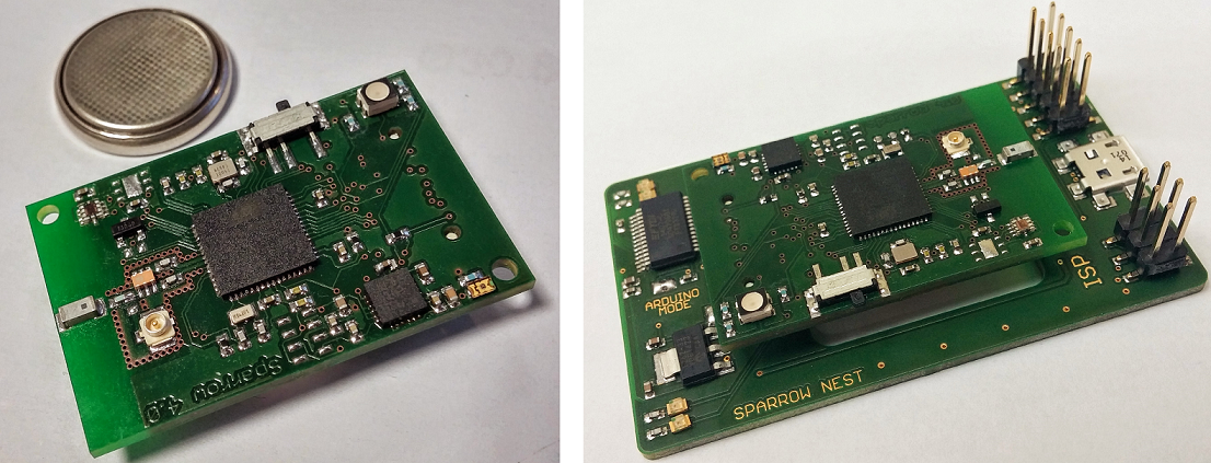
 Sparrow is an excellent platform for IoT, ultra low-power wireless computing and energy harvesting, with state-of-the-art sensing capabilities. It was designed to work with a range of wireless protocols, including IEEE 802.15.4, 6LoWPAN and ZigBee.
<imgcaption sparrowv4 | Sparrow v4 Sensor Node> </imgcaption>
Features include:
- Atmega128RFA1 8-bit AVR low-power microcontroller
- Integrated 2.4GHz radio transceiver
- Precision temperature & humidity sensor
- 9 DOF inertial unit
- Barometer/altimeter
- Light sensor (visible, IR and UV spectrum, luxmeter and UV radiation index)
- Fully-compatible with Arduino, with dedicated libraries for easy programming of the sensors and radio.
Installing the Arduino Libraries for the Sparrow Nodes
- Download Arduino
- Download and unzip the patch in a separate folder
- Locate the installation folder of Arduino on your drive (for Windows it's usually Program Files)
- Copy in Arduino\hardware\arduino\cores the contents of the folder sparrow_patch\Arduino\hardware\arduino\cores\sparrow
- Replace the file Arduino\hardware\arduino\boards.txt with sparrow_patch\Arduino\hardware\arduino\boards.txt
- Copy in Arduino\hardware\arduino\variants the folder named sparrow from sparrow_patch\Arduino\hardware\arduino\variants
- Restart the Arduino IDE
After a successful patch, you should be able to select a new board named Sparrow from the Tools>Board menu.
Connect the Sparrow Nest board through the supplied micro-USB cable to your computer and select the appropriate COM port from the Tools>Port menu

You're all set up!
Say Hello to the World
Now, let's run our first code, just to make sure everything is in order. Make sure to plug one Sparrow node into its socket on the nest board and connect the nest board to a USB port on your computer. Copy the code below and paste it in the Arduino IDE and then hit the Upload button.
/*
 * Blink
 *
 * The basic Arduino example.  Turns on an LED on for one second,
 * then off for one second, and so on...  We use pin 11 because,
 * on the Sparrow node it is connected to the green LED
 *
 * http://www.arduino.cc/en/Tutorial/Blink
 */


int ledPin = 11;                // LED (PB5) connected to digital pin 11

void setup()                    // run once, when the sketch starts
{
  pinMode(ledPin, OUTPUT);      // sets the digital pin as output
}


void loop()                     // run over and over again
{
  digitalWrite(ledPin, HIGH);   // sets the LED on
  delay(1000);                  // waits for a second
  digitalWrite(ledPin, LOW);    // sets the LED off
  delay(1000);                  // waits for a second
}
After compiling and uploading, the RGB LED on the Sparrow node should blink green once a second.
Shades and Colors
You can fully control the RGB LED and make it shine any color you wish in full 24-bit glory by playing with the intensity of the shades of Red, Green and Blue. You will need to use the analogWrite() function instead.
int greenLED = 11;     //green LED on Arduino pin 11
int redLED = 8;        //red LED on pin 8
int blueLED = 10;      //blue LED on pin 10

void setup()                    // run once, when the sketch starts
{
  pinMode(greenLED, OUTPUT);      // sets the digital pin as output
  pinMode(redLED, OUTPUT);
  pinMode(blueLED, OUTPUT);
}

void color(unsigned char red, unsigned char green, unsigned char blue) // controls the RGB LED
{
  analogWrite(redLED, 255-red);
  analogWrite(greenLED, 255-green);
  analogWrite(blueLED, 255-blue);
}

void loop()                     // run over and over again
{
  unsigned char color_rgb[3];

  // Start off with red.
  color_rgb[0] = 255;
  color_rgb[1] = 0;
  color_rgb[2] = 0;

  // Choose the colours to increment and decrement.
  for (int decColour = 0; decColour < 3; decColour += 1) {
    int incColour = decColour == 2 ? 0 : decColour + 1;

    // cross-fade the two colours.
    for(int i = 0; i < 255; i += 1) {
      color_rgb[decColour] -= 1;
      color_rgb[incColour] += 1;

      color(color_rgb[0], color_rgb[1], color_rgb[2]);
      delay(15);
}}}
<imgcaption leds | The RGB LED on the Sparrow Node> </imgcaption>
<tabcaption led_bytes|Led pinout>
| LED | uC PIN | Arduino Pin |
|---|---|---|
| R | PB4 | 8 |
| G | PB5 | 11 |
| B | PB6 | 10 |
</tabcaption>
Temperature and Humidity Sensor
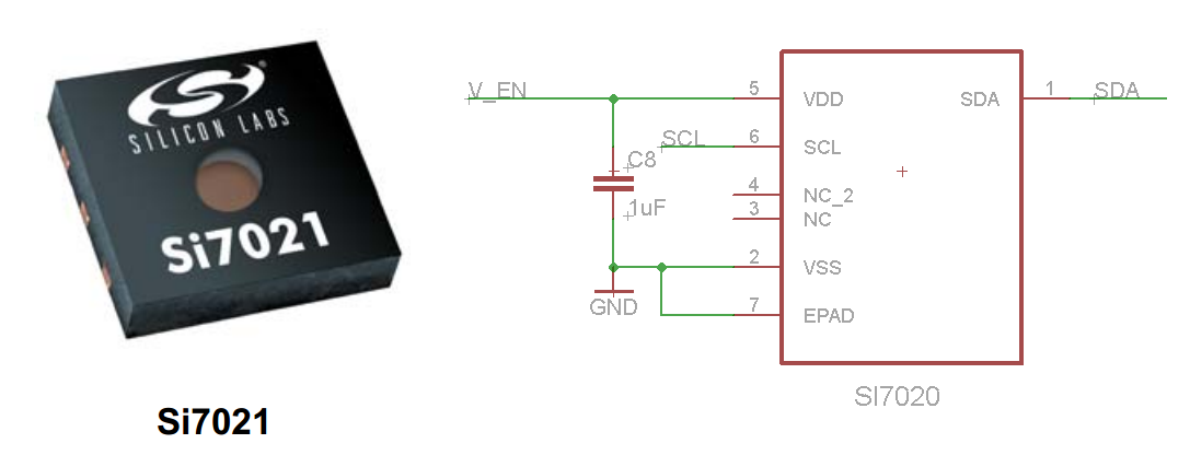
Si7021 is an integrated sensor that measures both temperature and relative humidity with good accuracy. The resolution of measured parameters can be selected through software between 8-12 bits for humidity and 12-14 bits for temperature. The sensor uses a digital I2C interface for data transmission, so we can easily interface with it using the Wire library.
<imgcaption humid | SI7020 and its connections to the the AVR microcontroller> </imgcaption>
We will need to use a dedicated library written specially for it. Download the library from here and unzip its contents into the folder named Arduino\libraries or use Arduino IDE's Add ZIP Library command.
#include <Wire.h>
#include <SHT2x.h>

int controlPin = 7;

void setup()
{
  pinMode(controlPin, OUTPUT);  //sensor on/off control

  Wire.begin();
  Serial.begin(9600);

  digitalWrite(controlPin, LOW); //enable all sensors
}

void loop()
{


  Serial.print("Humidity(%RH): ");
  Serial.print(SHT2x.GetHumidity());
  Serial.print("     Temperature(C): ");
  Serial.println(SHT2x.GetTemperature());

  //digitalWrite(controlPin, HIGH); //disable all sensors

  delay(1000);
}
Light Sensor
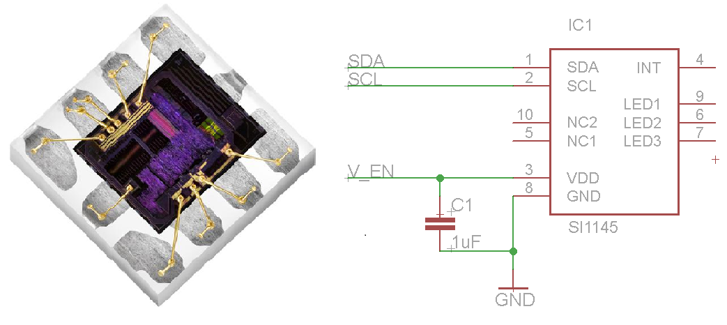
<imgcaption light | SI1145 ambient light sensor and AVR connection schematic> </imgcaption>
We will use the Adafruit_SI1145 library to interface with the sensor. Unzip the content of this zip file into the Arduino\libraries or use Arduino IDE's Add ZIP Library command.
#include <Wire.h>
#include "Adafruit_SI1145.h"

int controlPin = 7;
Adafruit_SI1145 uv = Adafruit_SI1145();

void setup() {
  pinMode(controlPin, OUTPUT);  //sensor on/off control
  delay(100);
  digitalWrite(controlPin, LOW);

  delay(1000);

  Serial.begin(9600);

  Serial.println("Adafruit SI1145 test");

  if (! uv.begin()) {
    Serial.println("Didn't find Si1145");
    while (1);
  }

  Serial.println("OK!");
}

void loop() {

  Serial.println("===================");
  Serial.print("Vis: "); Serial.println(uv.readVisible());
  Serial.print("IR: "); Serial.println(uv.readIR());

  // Uncomment if you have an IR LED attached to LED pin!
  //Serial.print("Prox: "); Serial.println(uv.readProx());

  float UVindex = uv.readUV();
  // the index is multiplied by 100 so to get the
  // integer index, divide by 100!
  UVindex /= 100.0;
  Serial.print("UV: ");  Serial.println(UVindex);

  delay(1000);
}
Barometer
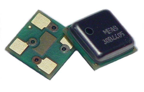
<imgcaption barometer | MS5637 barometer/altimeter> </imgcaption>
The Sparrow nodes are using the MS5637 pressure sensor for barometric and altimeter measurements. We will use the Freetronics library to interface with it.
#include <Wire.h>
#include <BaroSensor.h>
int controlPin = 7;

void setup()
{
  pinMode(controlPin, OUTPUT);  //sensor on/off control
  delay(100);

  digitalWrite(controlPin, LOW);

  Serial.begin(9600);
  BaroSensor.begin();
}

void loop()
{
  if(!BaroSensor.isOK()) {
    Serial.print("Sensor not Found/OK. Error: ");
    Serial.println(BaroSensor.getError());
    BaroSensor.begin(); // Try to reinitialise the sensor if we can
  }
  else {
    Serial.print("Temperature: ");
    Serial.println(BaroSensor.getTemperature());
    Serial.print("Pressure:    ");
    Serial.println(BaroSensor.getPressure());
  }
  delay(1000);
}
Radio Transmission
We will use the ZigduinoRadio library in order to send data between two or more Sparrow nodes. You can download the library from here.
Here's an example code:
/*

Run this sketch on two Zigduinos, open the serial monitor at 9600 baud, and type in stuff
Watch the Rx Zigduino output what you've input into the serial port of the Tx Zigduino

*/

#include <ZigduinoRadio.h>

void setup()
{
  ZigduinoRadio.begin(11);
  Serial.begin(9600);

  ZigduinoRadio.attachError(errHandle);
  ZigduinoRadio.attachTxDone(onXmitDone);
}

void loop()
{
  if (Serial.available())
  {
    ZigduinoRadio.beginTransmission();

    Serial.println();
    Serial.print("Tx: ");

    while(Serial.available())
    {
      char c = Serial.read();
      Serial.write(c);
      ZigduinoRadio.write(c);
    }

    Serial.println();

    ZigduinoRadio.endTransmission();
  }

  if (ZigduinoRadio.available())
  {
    Serial.println();
    Serial.print("Rx: ");

    while(ZigduinoRadio.available())
      Serial.write(ZigduinoRadio.read());

    Serial.println();
    Serial.print("LQI: ");
    Serial.print(ZigduinoRadio.getLqi(), 10);
    Serial.print(", RSSI: ");
    Serial.print(ZigduinoRadio.getLastRssi(), 10);
    Serial.print(" dBm, ED: ");
    Serial.print(ZigduinoRadio.getLastEd(), 10);
    Serial.println("dBm");
  }


  delay(1000);
}

void errHandle(radio_error_t err)
{
  Serial.println();
  Serial.print("Error: ");
  Serial.print((uint8_t)err, 10);
  Serial.println();
}

void onXmitDone(radio_tx_done_t x)
{
  Serial.println();
  Serial.print("TxDone: ");
  Serial.print((uint8_t)x, 10);
  Serial.println();
}

