Table of Contents
Microsal
Dental Implant With Contact Nano-Sensors for the Treatment of Xerostomia
Microsal represents the collaboration of multiple faculties with the purpose to create a third generation micro-embedded device meant to alleviate symptoms of xerostomia and also collect patient data regarding the condition in an unobstrusive way.
The current iteration of this project has already been investigated in a diploma project and already presented at an embedded devices conference and at a medical workshop with plans to demonstrate crrent research stages. This chapter will describe the current iteration and some of the design choices. Microsal represents the research efforts of multiple faculties to create a third-generation implant-supported neuro-electrostimulation embedded device. This research report will only report on the hardware/firmware/software details regarding the project. As described in the related work section, the device’s main goal is to electrically stimulate the bucal and lingual nerve in order to produce the salivary response and increase the comfort of the patient. Additionally, besides the stimulation logic, the design also includes 2 passive sensors that are used to objectively evaluate the current conditions of the patient. The information taken from the sensors will be used to determine if the patient’s condition is deteriorating or improving over time, providing valuable insight on the effectiveness of the treatment. This represents the next logical step for the evolution of the generational prototypes. Also, to facilitate communication to the device we have decided to use a chip that has a Bluetooth Low Energy component integrated inside. The NRF51822 chip, by Nordic Semiconductors fits the bill, being a highly advanced ARM microcontroller, with BLE functionality and extremely low power requirements The high level design is described in the design figures
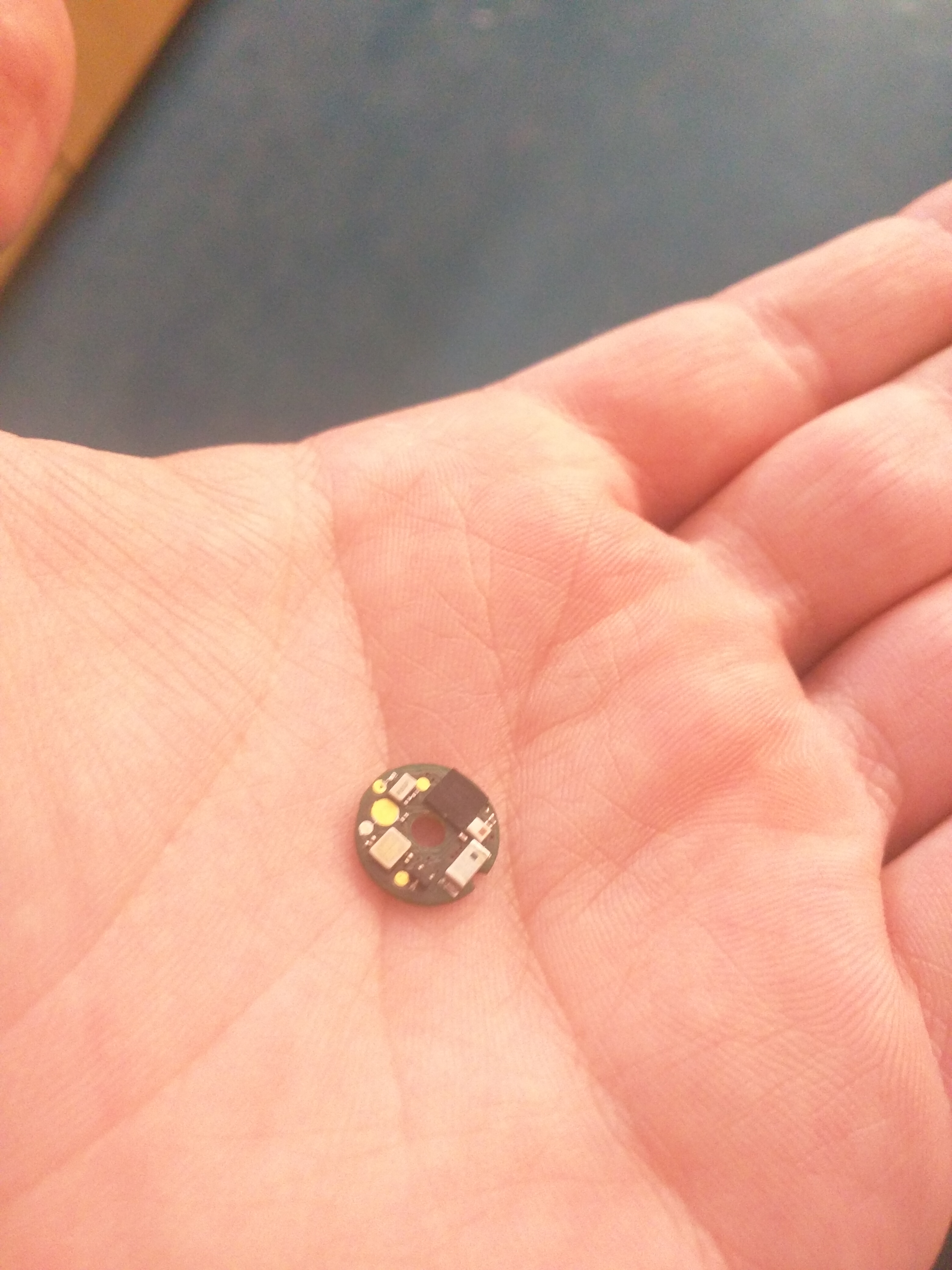
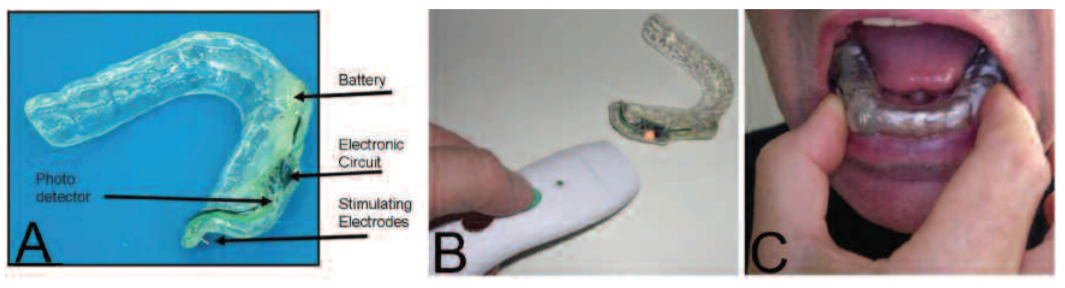
Relative size of the embedded device

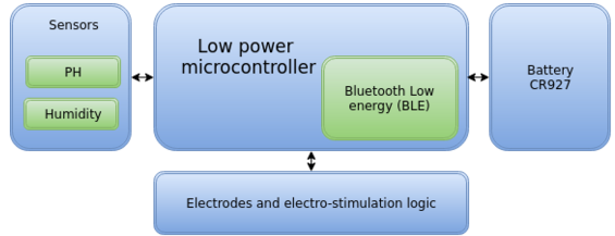
high level designs of the hardware
Requirements
After testing out the original version we realized that there is still room for improvement. The most important thing we must improve on is the size, currently the design fits inside a cylindrical case of 13.5×6 mm. There are 2 designs we are considering at the moment: one with a high degree of success sized 11.5×6 mm, and one that is incomplete, sized ~10×5.5. Each of these designs come with the assumption that the new design will not have the central hole present, and that a different set of batteries will be used (CR927 – 9×2.7 mm or a set of SR67 – 7.9×1.65, for a total of 7.9×3.3 mm used only by the batteries). The matter of the electronic design is still being internally debated. These new batteries will require additional phases of testing to see if they actually can provide power for enough time to be viable. Also, the Android reference application and the firmware must be updated to include the following features:
Sending sensor data in bulk Currently the Microsal device must be polled in order to obtain the sensor information. This modification would provide great advantages in battery saving, as the device can spend more time in the sleep phase, instead of constantly transmitting sensor data. This improvement would also mean setting up buffers and improving the communication protocol between the Microsal and the Android device. synchronization with timestamp This modification proposes creating a BLE characteristic that would represent an encoded structure that would report the pH and the humidity correlated with timestamp information. We are debating if there would be a need for the device to know the actual time or just the time since boot would be enough. Each approach has limitations and challenges. Better battery prediction Currently the batteries have very flat voltage drop off curves, meaning that without a strong correlation between battery characteristics and measurement capability, we are put in the position where the battery can simply fizzle out with little warning. UI improvements and separation of patient/doctor interfaces The final version of the Android application must have two different UIs, one for the patient, which only reports data for the user’s devices, and does not allow the user to reconfigure his device, and the medical technician version, that has discovery mechanisms and is capable of more advanced probing and configuration of current devices. Newer iterations of the design require far smaller dimensions for the device casing, which also means less available space for the batteries and electronics. The most important constraint and metric for the success of the project remains the size of the device, it must be reduced as much as possible in order to ensure user adoption. Currently, the device is large enough that teeth from lower and the upper jaw need to be sculpted in order for the device to be attached. Power optimizations For example, determine the lowest power configuration that still preserves the neuro-electro-stimulation effect. Another optimization that must be implemented is the monitoring and incorporating feedback loops from the sensors, a reasonable salivary response should not be over-stimulated. The second most important metric for the project’s success, after the device’s size, is the lifespan of the device’s battery. Naturally, a device with a longer span is to be desired, but a minimum battery life of several weeks is required in order to ensure user adoption. Note that the device cannot be recharged, as the electronic logic for charging simply cannot be integrated into such little space.
Waveform

Waveform pattern , composed of multiple sets of pulses. The sets of pulses are represented as blue and each individual pulse as green. The system works as well just in the presence of the positive front of each pulse.
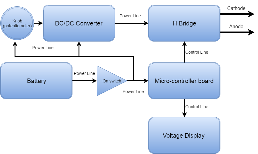
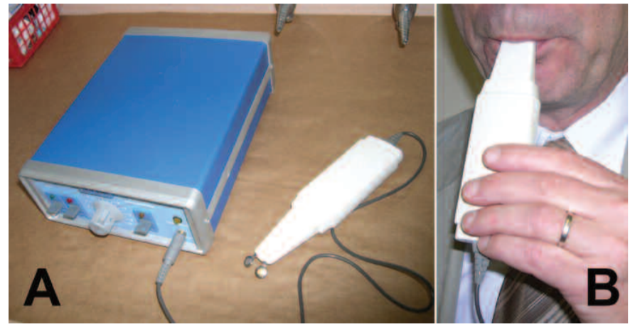
High level design of the prototype that was used in experimentally determining which values of the signal parameters are crucial

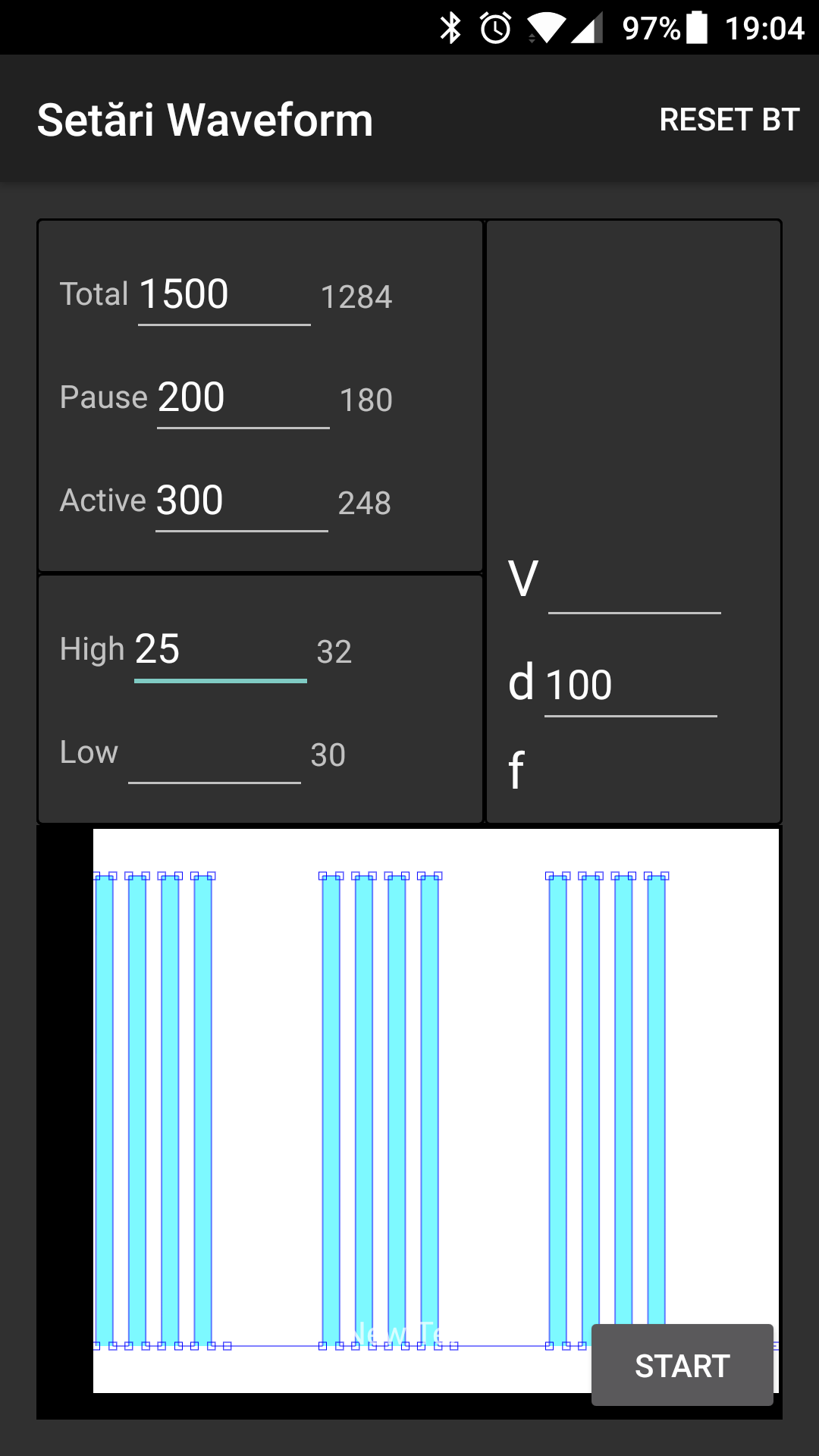
Android User Interface for the application that will communicate with the NRF51822 chip. The application is responsible for the waveform generation pattern and collecting data. The application is not bound to a particular device, it can connect to any device that match the specification
Results from clinical test
| Pulse length | Frequency | Voltage | Voltage swing | Effect | |
|---|---|---|---|---|---|
| 1 | 4 ms | 0.1 Hz | 3.25 V | positive | N |
| 2 | 4 ms | 1 Hz | 3 V | positive | P |
| 3 | 10 ms | 1 Hz | 3 V | positive | P |
| 4 | 10 ms | 2 Hz | 3 V | positive | P |
| 5 | 4 ms | 4 Hz | 3 V | positive | P |
| 6 | 4 ms | 8 Hz | 3 V | positive | P |
| 7 | 10 ms | 8 Hz | 3.25 V | positive | P |
| 8 | 10 ms | 8 Hz | 5 V | positive | P |
| 9 | 10 ms | 8 Hz | 5 V | both | P |
In order to have the required results, with a minimum of energy expenditure we set out to find a signal pattern that produces a measurable response. We started by describing all possible signal parameters (see the waveform explanatory image), and implementing the control hardware and software in order to enable all of them. We considered that a sinusoid approximation is enough to stimulate the neurons without harming nearby tissue. The assumption was supported by the experiment description at [3]. Experimentally (table above) we determined that the patient responds favorably to a wide range of stimulation patterns, the one notable difference being when we used a combination of low pulse duration, low frequency, and low voltage. These results will be applied in the power optimization phase of the next iteration).
Dimensions and casing
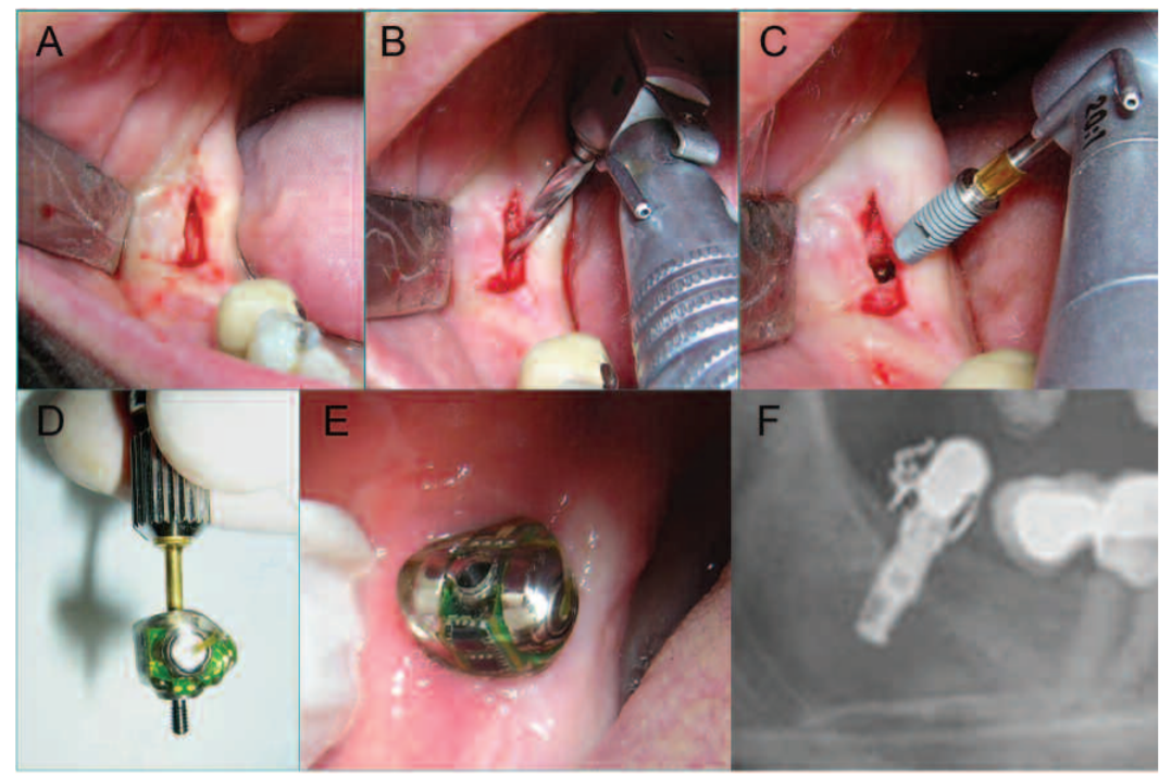
The device, once soldered will be stored in a bio-compatible metal cylinder casing, designed to provide protection and support. The casing will be attached similarly of a dental implant, inside the bone of the patient (3rd generation neuroelectrostimulation device). The casing is designed to provide the support and function of a real tooth, while not obstructing wireless communication.
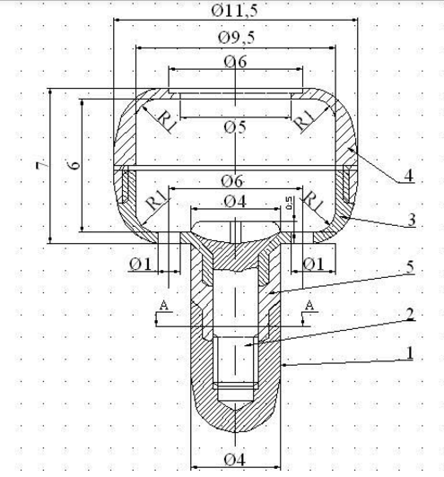
Design of the casing that will hold the device. Notice the fillet that allows for the upper part removal and the hole inside the upper cap that allows for wireless signal comunication
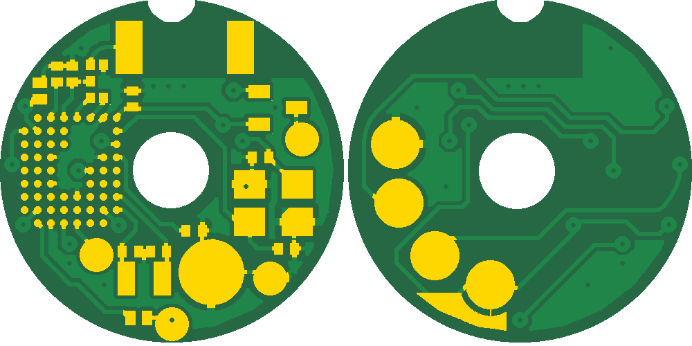
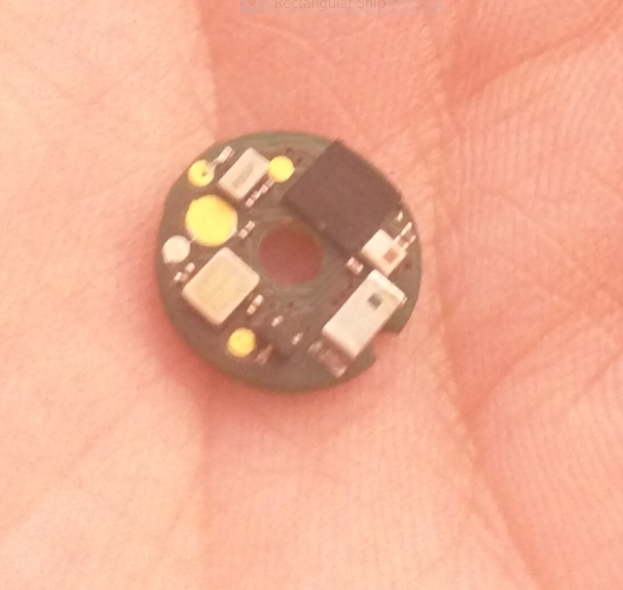
PCB design of the Microsal Embedded Device. Multiple pads are present in order to have add-on connection to the sensors, after the electrical components are soldered on
Bibliography
Workshop București 28.10.2016 Abordarea interdisciplinara a pacientului cu xerostomie; perspective actuale de diagnostic si tratament, PIM ed., Iasi, Romania, 2016. ISBN 978-606-13-3276-2.
Adrian Nitu, Dan Tudose, Dan Dragomir. (2016, Aug). Dental Implant With Contact Nano-Sensors for the Treatment of Xerostomia. Presented at RoEduNet
E. E. Harold Warner, E. David Martin, V. Speck, B. Nathan, “Electrostimulation of erection and ejaculation and collection of semen in spinal cord injured humans”, http://www.rehab.research.va.gov/ jour/86/23/3/pdf/warner.pdf, July 1986.
Porter SR, Konttinen YT. Fedele S1, Wolff A, Strietzel F, López RM. Neuroelectrostimulation in treatment of hyposalivation and xerostomia in sjögren’s syndrome: a salivary pacemaker. http://www.ncbi.nlm.nih.gov/pubmed/18671323, August 2008.
Working on
UI improve
Current pain points:
- create profiles for the stimulation parameters for each patient
- add UI method other than typing to update stimulation parameters
- create number of repetitions linked with TT
- draw how the signal will look
- show all patients, even the inactive ones
- tabbed ui for patients
Refactor the characteristics
Current pain points:
- add a time characteristic
- add historical data download characteristic, with pair ack characteristic
- will use a compression scheme
Log
| Week | Done | Learned |
|---|---|---|
| Week 6 (6.2-12.2) | Created wiki page | |
| Discussions about future features with Dan Dragomir | ||
| Week 10 (6.3-12.3) | Sync – Research direction meeting with DD | |
| Wiki – Updated wiki page with the next features | ||
| Android UI – Refactored Lookup activity to display all patients, improved the internal design of the application | ||
| UI redesign at 25% | ||
| Week 12 (20.3-26.3) | Android UI – Refactored Tooth Options Activity to render how the signal will look, improved the internal design of the application | |
| UI redesign at 75% |
Resources
